A network TAP (Test Access Point) is one of the most important and least discussed devices in a security-focused network infrastructure. It sits in the cable path between two network devices, creates a perfect copy of every packet that flows past, and delivers that copy to monitoring and security tools — without any impact on the production network. Unlike SPAN ports, which are software functions running inside switches, network TAPs operate at the physical signal level: they cannot drop packets, cannot be addressed by the network, and cannot be disabled by attackers. They are the foundation of production-grade network visibility.
This guide covers every aspect of network TAP technology: what a TAP is and how it works, the complete taxonomy of TAP types (passive fiber, active copper, bypass, and hybrid), how optical splitters work and how to calculate power budgets, the difference between FBT and thin-film splitters, when to use copper versus fiber TAPs, how to choose the right split ratio, when TAPs are required versus when SPAN is acceptable, and how Niagara Networks' TAP product line covers every deployment scenario from 1G copper to 400G optical.
1.1 TAP vs. SPAN: The Essential Comparison
Before covering TAP types, it is worth establishing why TAPs are the correct choice for production security monitoring, and when SPAN ports remain acceptable. This comparison comes up in nearly every network visibility discussion:
|
Dimension
|
Network TAP
|
SPAN / port mirroring
|
|
Packet loss
|
Zero — hardware split at signal level. Zero loss regardless of link utilisation
|
Lossy by design — switch deprioritises SPAN copies under load
|
|
CRC errors
|
Passed through — forensically complete including malformed frames
|
Silently dropped by switch before SPAN copy is made
|
|
VLAN tags
|
Preserved — all L2 headers exactly as on wire
|
Stripped by default on most Cisco platforms; re-enable requires explicit config
|
|
Bidirectional handling
|
Separate Tx and Rx monitor ports — zero oversubscription
|
Bidirectional 10G = 20Gbps aggregate on 10G SPAN port → mandatory oversubscription
|
|
Network impact
|
Passive: zero. Active: signal regeneration only
|
Consumes switch ASIC resources; misconfigured SPAN has caused outages
|
|
Security
|
No IP/MAC address — not network-addressable — tamper-proof
|
SPAN port is network-addressable; accessible to attackers via switch
|
|
Session limits
|
Unlimited simultaneous monitor connections to NPB/tools
|
2–8 concurrent sessions per switch (Cisco Catalyst platform-dependent)
|
|
Forensic admissibility
|
Hardware-level copy — court-admissible evidence
|
Software-processed — chain of custody cannot be guaranteed
|
|
Compliance mandates
|
Meets M-21-31, PCI DSS, HIPAA completeness requirements
|
Sampled/lossy — generally fails completeness requirements
|
|
Best for
|
All production security monitoring, compliance capture, high-utilisation links
|
Ad hoc troubleshooting, low-utilisation links, intra-switch traffic
|
The networking industry has converged on a clear best practice: TAP where you can, SPAN where you can't. For any link carrying security-critical traffic, compliance-mandated capture, or utilisation above 50%, a network TAP is the required approach. SPAN is acceptable for ad hoc troubleshooting on low-utilisation links, intra-switch traffic that cannot be accessed by physical TAP, and emergency situations where no maintenance window is available for TAP installation.
2. The Complete Network TAP Taxonomy

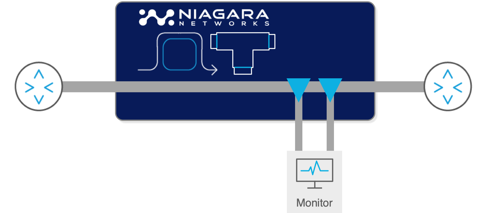
2.1 Passive Fiber TAPs (Optical TAPs)
A passive fiber TAP — also called a passive optical TAP — is the simplest and most reliable form of network TAP. It requires no power supply and uses a small piece of hardware called an optical splitter to physically divert a portion of the light signal from the cable to a monitoring port. The TAP has no electronics, no firmware, and no configuration — it is purely optical.
Because a passive TAP requires no power to operate, it has a unique failure property: it cannot fail in a way that disrupts the production link. If the TAP housing is physically damaged, the worst outcome is that the monitoring copy is lost — the production fibre path through the TAP device remains intact via the passive splitter. This makes passive TAPs the preferred choice for critical links where any risk of production disruption is unacceptable.
Passive fiber TAPs are available in two internal splitter technologies:
Fused biconical taper (FBT): The traditional method. Two optical fibres are thermally fused together so that a portion of the light from one fibre is coupled into the other. The analogy is a river fork: light is diverted the same way water divides at a fork. FBT splitters are low-cost and work well for 1G short-range links, but are less suitable for high-speed links (10G and above) because of uneven light distribution.
Thin-film splitter: Uses a semipermeable membrane — like a semi-reflective glass surface — placed across the optical fibre at an angle. A portion of the light passes through; the rest is reflected toward the monitoring port. Thin-film splitters are more expensive but have significantly lower insertion loss at high speeds, more even light distribution across the fibre core, and support for multiple simultaneous wavelengths. Thin-film is the correct choice for 10G and above, and is the only option for Cisco 40G BiDi links.
2.2 Split Ratios: Understanding Light Division
The split ratio specifies how much of the optical signal continues to the production network and how much is diverted to the monitoring port. It is expressed as two percentages that sum to 100: network percentage / monitor percentage. A 70/30 split sends 70% of light to the network and 30% to the monitoring port.
The guiding principle is to allocate as much light as possible to the production network to minimise the risk of signal degradation. This is why the first number (network percentage) is always larger. The question is how much monitoring margin is available. The following table gives the maximum insertion loss values for each split ratio across multimode and singlemode fibre:
|
Split ratio (network/monitor)
|
Max network loss (MM)
|
Max monitor loss (MM)
|
Max network loss (SM)
|
Best use case
|
Niagara 3225
|
|
50/50
|
3.9 dB
|
3.9 dB
|
3.7 dB
|
Most common. 10G/100G with adequate light budget
|
✓
|
|
60/40
|
3.15 dB
|
5.15 dB
|
3.05 dB
|
When marginal light levels require extra network margin
|
✓
|
|
70/30
|
2.2 dB
|
6.2 dB
|
2.0 dB
|
1G short-range links with adequate budget. Not for 10G multimode
|
✓
|
|
80/20
|
1.5 dB
|
7.5 dB
|
~1.3 dB
|
Very tight light budgets. Monitor quality reduced significantly
|
Optional
|
Practical guidance: for most 10G multimode deployments, a 50/50 split is appropriate and the most commonly deployed ratio. For 1G links with long cable runs, a 70/30 split preserves more light for the production signal. Gigamon's published recommendation is to avoid 70/30 for 10G multimode due to tight light margins.
2.3 Power Budget Calculations — The Critical Step
The most important step before deploying a passive optical TAP is calculating the optical power budget to confirm that adequate light margin exists for the chosen split ratio. Insufficient light causes the receiving transceiver to misinterpret the signal, dropping packets on the production network — which defeats the purpose of the TAP entirely.
The power budget calculation follows these formulas:
Power Budget = Transmitter Power (min) − Receiver Sensitivity
Cable Attenuation = Attenuation rate (dB/km) × cable length (km)
Connection Loss = 0.5 dB × number of connectors in path
Total Cable Plant Loss = Cable Attenuation + Connection Loss
Power Margin = Power Budget − Total Cable Plant Loss
TAP fits if: Power Margin > TAP insertion loss (from split ratio table)
The following worked examples compare 1G and 10G scenarios to illustrate why power budget calculations are critical — the same 50/50 TAP that comfortably fits a 1G link may fail on a 10G link:
|
Parameter
|
1000BASE-SX on OM2 (10m)
|
10GBASE-SR on OM3 (10m)
|
|
Transmitter power (min)
|
−9.5 dBm
|
−7.3 dBm
|
|
Receiver sensitivity
|
−17.0 dBm
|
−11.1 dBm
|
|
Power budget (Tx − RxSens)
|
7.5 dB
|
3.8 dB
|
|
Cable attenuation (3.5 dB/km × 0.01 km)
|
0.035 dB
|
0.035 dB
|
|
Connector loss (2 connectors × 0.5 dB)
|
1.0 dB
|
1.0 dB
|
|
Total cable plant loss
|
1.035 dB
|
1.035 dB
|
|
Power margin before TAP
|
6.465 dB
|
2.765 dB
|
|
50/50 TAP loss (max, multimode)
|
3.9 dB → margin 2.565 dB ✓
|
3.9 dB → margin −1.135 dB ✗ (insufficient!)
|
|
70/30 TAP loss (max, multimode)
|
2.2 dB → margin 4.265 dB ✓
|
2.2 dB → margin 0.565 dB ✓ (marginal — verify with real values)
|
|
Conclusion
|
50/50 TAP fits comfortably
|
50/50 may fail — use 70/30 or active TAP. Verify with actual transceiver specs.
|
The lesson from these numbers is clear: always calculate the specific power budget for each link before selecting a split ratio. Use the actual transceiver specifications where available, not just the IEEE minimum values. Actual manufacturer optic specifications are typically better than IEEE minimums, often giving several additional dB of margin.
2.4 Optical Fibre Types: OM1 Through OS2
Passive TAPs are specific to the fibre type and speed they are designed for. Unlike switches and NPBs, a passive TAP does not change the speed or wavelength of the signal — it copies it exactly. This means a TAP must be matched to the cable type, speed, and transceiver wavelength of the link it monitors:
|
Cable type
|
Core (µm)
|
Colour
|
Connector
|
Max speed
|
Max reach
|
Splitter for TAP
|
|
OM1 multimode
|
62.5/125
|
Slate/beige
|
LC
|
1G
|
275m (1000BASE-SX)
|
FBT or thin-film
|
|
OM2 multimode
|
50/125
|
Orange
|
LC
|
1G / 10G
|
550m (1G), 82m (10G)
|
FBT or thin-film
|
|
OM3 multimode
|
50/125
|
Aqua
|
LC / MPO
|
10G / 40G / 100G
|
300m (10G), 100m (100G)
|
Thin-film recommended
|
|
OM4 multimode
|
50/125
|
Aqua
|
LC / MPO
|
Up to 400G
|
550m (10G), 150m (100G)
125m (400G)
|
Thin-film required
|
|
OM5
multimode
|
50/125
|
Lime Green
|
LC/MPO
|
Up to 800G
|
550m (10G)
150m (100G)
150m (400G)
|
Thin-film required
|
|
OS1/OS2 singlemode
|
9/125
|
Yellow
|
LC
|
Up to 400G
|
2–40km (OS1/OS2)
|
Thin-film required
|
|
40G Cisco BiDi
|
50/125 OM3/OM4
|
Aqua
|
LC (dual-wavelength)
|
40G
|
100–150m
|
Thin-film BiDi only
|
Critical point for multi-speed environments: Niagara Networks' modular 3225 chassis supports up to 24 single-width TAP modules or up to 12 dual-width modules, accommodating up to 36 TAP links in a single 1U appliance. Each module is independently specified for the target fibre type and speed, allowing mixed-speed data centres to use a single TAP chassis across diverse link types.
2.5 The Cisco 40G BiDi TAP: A Special Case
Cisco's 40G BiDi (Bidirectional) technology uses a single LC fibre pair to achieve 40G by transmitting two wavelengths simultaneously in each direction — 850nm and 900nm on standard OM3/OM4 fibre. This significantly reduces cabling cost in leaf/spine architectures but creates a specific TAP requirement: only thin-film splitters can handle bidirectional multi-wavelength operation.
FBT splitters cannot effectively split multiple wavelengths simultaneously on the same fibre pair, making them unsuitable for 40G BiDi deployments. Any passive TAP deployed on a Cisco BiDi link must specifically be a thin-film BiDi TAP — a product category that most general-purpose TAP vendors do not carry. Niagara Networks' 3225 modular chassis includes dedicated BiDi TAP modules rated for Cisco's specific wavelength requirements.
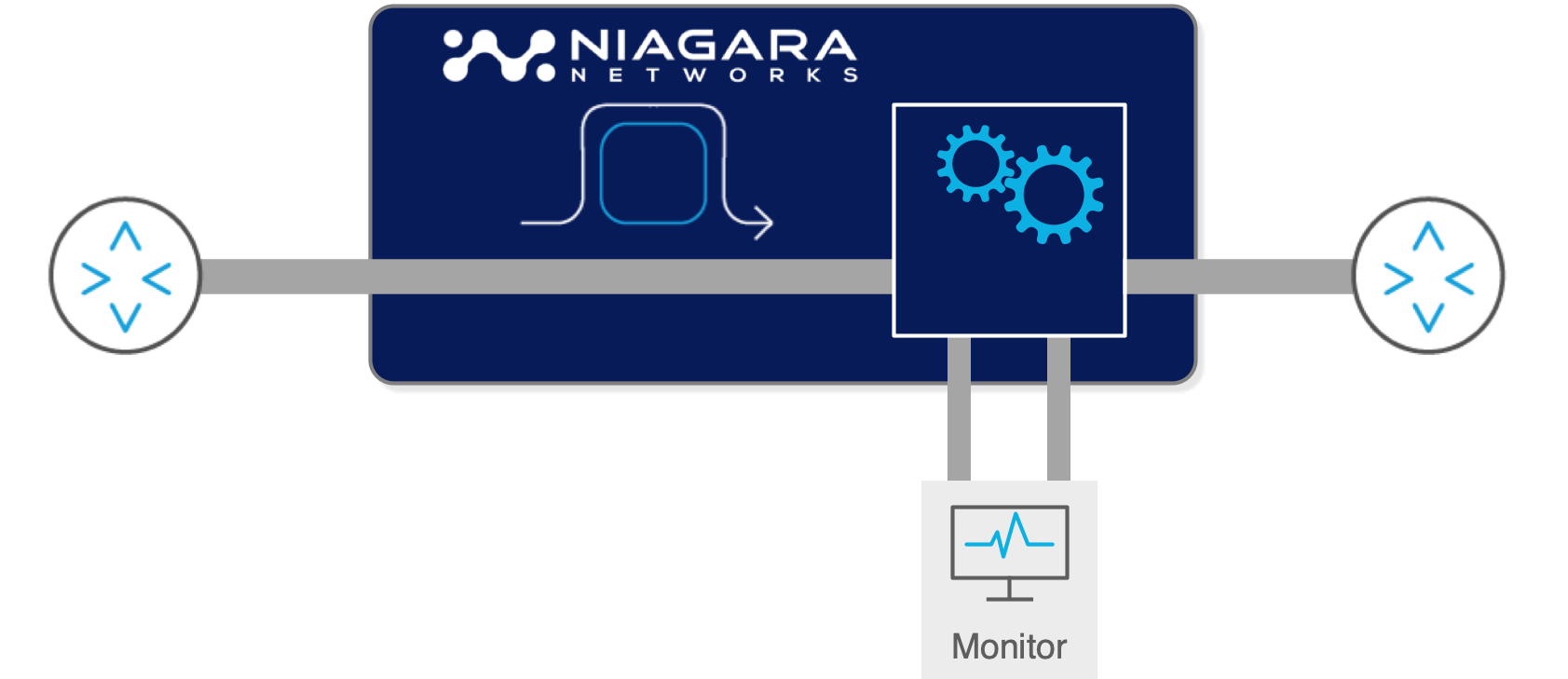
3. Active TAPs: Copper Ethernet and Signal Regeneration
Active network TAPs require a power source to operate. Instead of passively splitting the signal, they receive the incoming signal, regenerate it at full strength, and transmit two separate output signals: one to the production network destination and one to the monitoring port. This regeneration approach has both advantages and disadvantages compared to passive TAPs.
3.1 When Active TAPs Are Required
Active TAPs are required — not optional — in four specific situations:
1. Copper Ethernet networks: Passive splitters only work with optical signals. Copper Ethernet uses electrical signals carried on twisted-pair cable. Active TAPs for copper use electrical signal regeneration. The most common copper TAP scenarios are workstation networks (1G RJ45), server iDRAC/management interfaces, IoT networks, and OT/ICS devices running Ethernet.
2. Insufficient light budget for passive TAP: When a passive split ratio calculation shows negative margin, an active TAP eliminates the light budget problem entirely: signal regeneration means the monitoring copy is generated at full strength regardless of the original signal quality.
3. Signal type conversion: Since an active TAP regenerates the signal anyway, it can simultaneously perform media conversion — for example, receiving a 10G SR (short-range, multimode) signal and retransmitting it as 10G LR (long-range, singlemode) to a monitoring tool located far from the capture point.
4. TwinAx and direct-attach copper (DAC): TwinAx cables use fixed SFP+ modules — there is no fibre to splice and no way to insert a passive splitter. Active TAPs that terminate and regenerate the signal provide the only TAP option for these link types.
3.2 Active TAP Failsafe Design
The critical concern with active TAPs is their power-dependent operation. If an active TAP loses power, it may create a link failure — the production traffic path goes down. This is an unacceptable failure mode for critical infrastructure.
Niagara Networks' active copper TAPs address this with Failsafe Bypass Technology: a hardware relay switch that closes automatically on power loss, creating a direct electrical connection that bypasses the TAP electronics. The monitoring copy is lost on power failure, but the production link remains operational. This fail-open behaviour is the appropriate default for most deployments.
3.3 Aggregation Mode in Active TAPs
Active TAPs offer a capability that passive TAPs cannot: aggregation mode. In split mode (the passive default), the Tx stream from endpoint A is delivered to monitor port 1 and the Tx stream from endpoint B is delivered to monitor port 2. This correctly prevents oversubscription — a 10Gbps bidirectional link delivers two separate 10Gbps monitoring streams.
In aggregation mode, an active TAP combines both directions into a single monitoring port output, using internal buffering to handle any simultaneous packet collision. This is useful when the monitoring tool can accept a combined full-duplex stream and the link utilisation is low enough that simultaneous transmission from both directions is rare. An NPB connected to the aggregated output can then deduplicate and separate flows if needed. Niagara Networks' bypass switches and packet brokers with active TAP functionality support configurable split/aggregate mode.
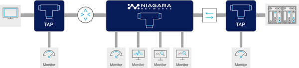
4. Bypass TAPs: Protecting Inline Security Tools
A bypass TAP — also called a bypass switch or inline bypass — is a specialised active TAP that serves two simultaneous functions: it provides TAP monitoring copies of all traffic on the link, and it protects an inline security tool (IPS, NGFW, WAF, DDoS mitigation device) from becoming a single point of failure.
4.1 The Inline Tool Problem
Inline security tools are inserted into the production traffic path — every packet must pass through the tool before continuing to its destination. This provides the highest-quality inspection but creates a structural risk: if the inline tool fails (power loss, software crash, firmware update), the traffic path fails with it. A 10-second IPS reboot becomes a 10-second network outage for all traffic that passes through it.
The bypass TAP solves this by sitting between the production link and the inline tool, with a failover relay that bypasses the tool on failure. Normal operation sends all traffic to the inline tool and back; failure detection (via heartbeat packets) triggers the relay to connect the link directly, maintaining traffic flow. The tool's failure becomes invisible to the production network.
4.2 Bypass TAP Operation: Heartbeat Detection
The bypass TAP continuously sends heartbeat packets to the inline tool and monitors for responses. The heartbeat is typically a small synthetic packet on a configurable interval (e.g., 100ms). If heartbeat responses stop arriving within a timeout window, the bypass TAP concludes that the inline tool has failed and triggers the bypass relay.
This detection mechanism is faster and more reliable than SNMP-based health monitoring because it tests the actual packet forwarding function of the inline tool, not just its management plane availability. A tool that is up and responding to management queries but has stopped forwarding production traffic will be correctly detected as failed by heartbeat monitoring.
When the inline tool recovers, the bypass TAP detects the return of heartbeat responses and gradually restores traffic to the tool — typically using a configurable ramp-up to avoid traffic spikes.
4.3 The Hybrid Bypass: TAP + Bypass + Packet Broker in One
Niagara Networks' 3299 hybrid bypass is a product that combines inline bypass TAP functionality with a fully featured network packet broker in a single appliance. Instead of deploying three separate devices — a passive TAP for out-of-band monitoring, a bypass switch for the inline IPS, and a packet broker for traffic optimisation — the 3299 integrates all three functions and reduces hardware costs by over 50%.
The 3299 supports L2–L4 filtering, five-tuple matching, UDB filtering, tunnel handling (VLAN, MPLS), and load balancing with session stickiness. It captures 1G traffic, aggregates it into high-speed 10G uplinks, applies advanced filtering, and provides inline bypass protection — all in a compact, dual-redundant-power form factor available in AC and DC power models.
The 3808E is the 3299’s big brother supporting all the features detailed above but for 10G/25G/100G environments with carrier-grade failover. It also supports up to 8x 100G network segments in 1RU, the highest density available in the marketplace.
5. How to Choose a Network TAP: A Decision Framework
Selecting the right TAP type for a given link requires answering a structured set of questions. The following framework guides that decision:
Step 1: What media type is the link?
- Copper RJ45 (Cat 5e/6A): Must use active copper TAP with Failsafe Bypass. No passive option exists for copper.
- Optical fibre: Both passive and active are options. Proceed to step 2.
- TwinAx / DAC: Must use active TAP that terminates SFP+ connections.
Step 2: Is there an inline security tool on this link?
- Yes: Deploy a bypass TAP (3808E, 3299, or 3296 passive bypass) to protect the inline tool. The bypass also provides TAP functionality.
- No: Deploy a standard passive or active TAP depending on light budget and media type.
Step 3: Is this a Cisco BiDi link (40G)?
- Yes: Must use thin-film BiDi TAP. FBT splitters do not support multi-wavelength bidirectional operation.
- No: Proceed to step 4.
Step 4: Calculate the optical power budget (fibre TAPs only)
Using the formulas in Section 2.3: Power Budget = Transmitter Power − Receiver Sensitivity. Subtract cable plant loss (cable attenuation + connector losses). If Power Margin > TAP insertion loss for 50/50 split: deploy passive 50/50 TAP. If Power Margin only supports 70/30: deploy passive 70/30 TAP (note: not recommended for 10G multimode). If no split ratio fits: deploy active TAP (regeneration eliminates light budget constraints).
Step 5: How many tools need to see this traffic?
- One tool: TAP directly to tool or to NPB input.
- Multiple tools: TAP to NPB input. NPB replicates and routes traffic to each tool. Do not attempt to chain multiple monitoring tools off a single TAP monitor port without an NPB — this creates its own oversubscription problem.
The following table maps common deployment scenarios to recommended TAP types:
|
Network location
|
Traffic type
|
Recommended TAP
|
Notes
|
|
DC core/distribution links (fibre)
|
High-volume inter-tier
|
Passive fiber TAP 50/50
|
Critical capture point; TAP before inline security tools
|
|
Server uplinks (10G/25G SFP)
|
Server-to-fabric
|
Passive fiber 50/50 or active
|
High utilisation — TAP required; SPAN will drop under load
|
|
Copper LAN (1G RJ45)
|
Workstation, IoT
|
Active copper TAP with Failsafe
|
Must use active; ensure battery backup for failsafe
|
|
Inline IPS / FW / WAF path
|
All inspected traffic
|
Bypass TAP (3808E/3299)
|
Inline tool protection AND TAP function simultaneously
|
|
WAN / Internet handoff
|
North-south traffic
|
Passive fiber TAP
|
Install at maintenance window; coordinate with carrier if collocated
|
|
40G fibre (spine/leaf)
|
Spine-leaf fabric
|
Passive or active 40G (BiDi if Cisco)
|
Check for Cisco BiDi — requires thin-film BiDi TAP specifically
|
|
100G / 400G DC links
|
Ultra-high-speed fabric
|
Passive thin-film 50/50 or active
|
Carefully calculate power budget — use Niagara 3225 modular
|
|
OT / ICS networks
|
Industrial protocols
|
Ruggedised TAP (extreme temp)
|
Modbus, DNP3, BACnet visible to NPB DPI after TAP capture
|
|
Cloud/VM environments
|
East-west VM traffic
|
CIT virtual TAP (no physical option)
|
Physical TAPs cannot reach this traffic; CIT required
|
6. TAP Type Comparison Reference Table
|
Property
|
Passive fiber
|
Active fiber
|
Active copper
|
Bypass TAP
|
Hybrid bypass
|
|
Requires power
|
No
|
Yes
|
Yes (always)
|
Yes
|
Yes
|
|
Failure mode (power loss)
|
Transparent — link continues
|
Fails open (with relay backup)
|
Fails open (Failsafe Bypass)
|
Relay closes → link preserved
|
Relay closes → link preserved
|
|
Network media
|
Fibre only
|
Fibre
|
Copper (RJ45/SFP)
|
Optical or copper
|
Optical or copper
|
|
Speed range
|
1G–400G
|
1G–100G
|
10/100M–10G
|
1G–100G
|
1G–100G
|
|
Light budget impact
|
Yes — split ratio reduces signal
|
None — signal regenerated
|
N/A — electrical
|
Minimal — relay-based
|
Minimal
|
|
Signal conversion
|
No
|
Yes (SR↔LR, etc.)
|
No
|
No
|
No
|
|
Passes CRC errors
|
Yes — all frames
|
Yes
|
Yes
|
Yes
|
Yes
|
|
Aggregation mode
|
No
|
Optional
|
Yes
|
Optional
|
Yes
|
|
Inline tool protection
|
No
|
No
|
No
|
Yes — primary function
|
Yes + packet brokering
|
|
Configuration required
|
None — plug and play
|
Minimal — port config
|
Minimal
|
Heartbeat + failover policy
|
Flow-map policy
|
|
Niagara product
|
3225 modular passive TAP
|
Integrated in bypass / NPB
|
3299 / bypass series
|
3808E, 3299, 3296
|
3808E + Packetron
|
7. Network TAP Best Practices
The industry has converged on a set of deployment best practices that minimize risk and maximize visibility effectiveness:
- TAP during initial network build: Installing a TAP on an existing live cable requires brief link downtime. Installing during initial cabling is zero-downtime. The cost of deferring TAP installation to a future maintenance window is incident-response delay when a breach occurs on an unmonitored link.
- TAP-All best practice: Deploy TAPs on every critical link during the design phase, even if active monitoring is not immediately planned. Pre-installed TAPs allow immediate forensic capture during security incidents without emergency change windows.
- Match TAP to cable type and speed: Passive TAPs are built for specific fibre modes and speeds. A TAP rated for OM2 10G will not correctly split an OS1 singlemode signal. Confirm fibre type and speed before ordering.
- Use new cabling at TAP installation: TAP failures are most commonly caused by bad connections, not TAP hardware. Use new patch cables, properly clean all connectors, and never mix cable types within a link.
- Verify with OTDR before finalising: Use a handheld Optical Time-Domain Reflectometer (OTDR) to measure actual cable plant loss and confirm that the power budget calculation was correct before putting the link into production.
- Never route monitoring traffic back through the production switch: Connect TAP monitor ports directly to an NPB or monitoring tool, not to a SPAN port on the same switch. This defeats the purpose of the TAP and re-introduces SPAN limitations.
- Document split ratios: Record the split ratio, cable lengths, transceiver models, and power budget calculations for every TAP installation. Future link upgrades or transceiver replacements may require recalculation.
8. Niagara Networks' Network TAP Product Line
Niagara Networks designs and manufactures its full TAP product range in Silicon Valley, USA — an important differentiator for government agencies, defence contractors, and regulated industries with supply chain security requirements. The product line covers every TAP use case:
3225 modular passive TAP chassis: Supports up to 24 single-width TAP modules or 12 dual-width modules providing up to 36 TAP links in a single 1U 19-inch rack space. Modules cover OM1/OM2/OM3/OM4/OM5 multimode and OS1/OS2 singlemode fibre at speeds from 1G through 400G. Dedicated BiDi modules for Cisco 40G deployments. Users can specify network/monitor split ratios (50/50, 60/40, 70/30) per module to match individual link power budgets.
3808E hybrid bypass switch: Multi-purpose appliance combining inline bypass protection (for IPS, NGFW, WAF, DDoS mitigation), active TAP functionality, and packet broker intelligence in a single platform. Supports 10G/25G/100G optical and copper interfaces. Heartbeat-based failover with configurable detection intervals.
3299 hybrid copper bypass: Compact all-in-one for 1G/10G copper and fibre environments. Combines bypass TAP, 1G copper active TAP, and packet broker with L2–L4 filtering, load balancing, and tunnel handling. Reduces hardware costs by over 50% compared to separate TAP, bypass, and broker devices.
3296 passive bypass: Optical relay-based passive bypass for environments requiring power-loss transparency on the bypass path as well as the TAP path.
Active TAP integrated in NPB and bypass products: Every Niagara bypass switch and NPB can be configured to function as an active TAP, providing monitoring output alongside its primary function without requiring additional hardware.
Frequently Asked Questions
What is a network TAP?
A network TAP (Test Access Point) is a hardware device inserted into a network cable between two network endpoints that creates a copy of all packets flowing on the link and delivers those copies to monitoring ports for analysis by security and monitoring tools. Unlike SPAN ports, which are software functions within switches, TAPs operate at the physical signal level — for optical fibre they use an optical splitter to divide the light signal, and for copper they use electronic signal regeneration. TAPs have no IP address, no MAC address, and cannot receive traffic on monitoring ports, making them tamper-proof and completely transparent to the network.
What is the difference between a passive fiber TAP and an active TAP?
A passive fiber TAP requires no power and uses an optical splitter (either FBT or thin-film technology) to physically divide the optical signal. It has no electronics, requires no configuration, and cannot fail in a way that disrupts the production link. An active TAP requires a power source, receives the incoming signal, and retransmits full-strength copies to both the production network and the monitoring port. Passive TAPs are preferred when the optical power budget allows; active TAPs are required for copper Ethernet (which cannot use optical splitters), for links with insufficient light budget, and for signal type conversion.
What is tap in networking / what is a test access point?
In networking, 'TAP' stands for Test Access Point (or sometimes Traffic Access Point). It refers to a dedicated hardware device that creates non-intrusive, zero-loss copies of network traffic for monitoring, security analysis, compliance capture, and forensic investigation. The term distinguishes this hardware-based approach from software-based SPAN ports (which drop packets under load) and from inline tools (which actually process and potentially block traffic). A network TAP's fundamental property is that it passively observes traffic without affecting it — the network has no knowledge that a TAP is present.
What is a split ratio and how do I choose one for a passive optical TAP?
The split ratio of a passive optical TAP specifies how much of the optical signal continues to the production network versus how much is diverted to the monitoring port, expressed as two percentages summing to 100 (e.g., 70/30 means 70% to the network, 30% to the monitor). The guiding principle is to preserve as much light as possible for the production network. To choose the correct split ratio, calculate the optical power budget: subtract cable plant loss (cable attenuation + connector losses) from the power budget (transmitter power minus receiver sensitivity). If the remaining margin exceeds the TAP's insertion loss for a given split ratio, that ratio is safe to deploy. 50/50 is the most common ratio for 10G and above; 70/30 is used for 1G short-range links. Gigamon recommends against 70/30 for 10G multimode due to tight margins.
When should I use a network TAP versus a SPAN port?
Use a network TAP for: all production security monitoring (IDS, NDR, SIEM feeds, compliance capture); links with utilisation above 50% where SPAN drops are certain; forensic or compliance capture where completeness must be guaranteed; and any link where the loss of monitoring traffic during peak-load periods is unacceptable. Use a SPAN port for: ad hoc, short-duration troubleshooting on low-utilisation links; monitoring intra-switch traffic that no physical cable can be TAP'd; emergency investigations where no maintenance window is available; and remote sites with modest traffic where TAP deployment cost is not justified. The axiom used across the industry is: TAP where you can, SPAN where you can't.
What is an optical TAP / passive optical TAP?
An optical TAP, passive optical TAP, or passive fiber optic TAP is a network TAP designed for fibre-optic cable that uses an internal optical splitter to create a monitoring copy of the light signal without using any power. The term 'optical' refers to the signal type (light rather than electrical), and 'passive' refers to the absence of electronics or power requirements. Optical TAPs are available for all common fibre types (OM1, OM2, OM3, OM4 multimode; OS1, OS2 singlemode) and speeds from 1G to 400G. They are the preferred choice for fibre networks with adequate optical power budget because they have no electronics to fail and no power dependency.
What is the difference between FBT and thin-film optical splitters?
FBT (fused biconical taper) and thin-film are the two internal splitter technologies used in passive optical TAPs. FBT splitters work by thermally fusing two fibres together so light is diverted at the fusion point — like a river fork. They are lower-cost and suitable for 1G links. Thin-film splitters work by placing a semipermeable membrane across the fibre that reflects a portion of the light to the monitoring port. Thin-film has lower insertion loss at high speeds (10G, 40G, 100G), more even light distribution across the fibre core, and the ability to split multiple wavelengths simultaneously. Thin-film is required for 40G Cisco BiDi links and strongly recommended for any speed of 10G or above.
What is an ethernet tap / copper ethernet tap?
An Ethernet TAP or copper Ethernet TAP is an active network TAP designed for copper Ethernet links (typically RJ45 Cat5e/Cat6A). Copper Ethernet cannot use passive optical splitters because it carries electrical rather than optical signals. Copper TAPs receive the incoming electrical signal, regenerate it at full strength, and transmit two separate copies: one to the production Ethernet endpoint and one to the monitoring port. Niagara Networks' copper TAPs include Failsafe Bypass Technology — a hardware relay that closes on power loss to maintain the production Ethernet link even if the TAP loses power. Copper TAPs are typically used for workstation networks, server management interfaces, IoT devices, and OT/ICS networks using standard Ethernet cabling.
Conclusion
Network TAPs are the foundation of production-grade network visibility. They are the only traffic capture mechanism that provides zero packet loss, forensic completeness, and tamper-resistance simultaneously — properties that no software-based SPAN port can match. The choice between TAP types is primarily driven by media type (fibre vs. copper), optical power budget, and deployment context (out-of-band monitoring vs. inline tool protection).
The hierarchy is clear: passive optical TAPs for fibre links with adequate light budget; active copper TAPs for Ethernet links; bypass TAPs wherever inline security tools need protection against creating network outages; and hybrid bypass devices (Niagara 3299, 3808E) wherever combining TAP, bypass, and packet broker functions in a single device reduces hardware cost and complexity. In all cases, the TAP output should be processed by a Network Packet Broker before reaching security tools — to deduplicate, filter, enrich with application intelligence, and decrypt TLS sessions for the tools that need it.
Niagara Networks manufactures the complete TAP-to-NPB stack in Silicon Valley, USA — passive optical TAPs from 1G to 400G in the 3225 modular chassis, active copper TAPs with Failsafe Bypass, inline bypass switches in the 3808E/3299/3296 series, and NPBs with Packetron intelligence — providing the end-to-end visibility architecture that your security and operations infrastructure requires. To select the right TAP configuration for your network, visit niagaranetworks.com.


.svg)
.svg)

